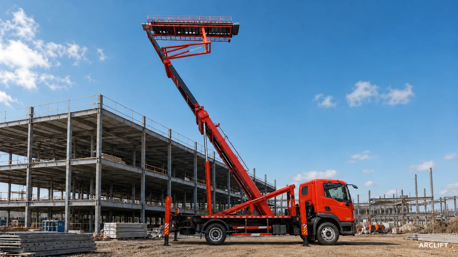
Choose the mobility architecture before choosing a model number. A crawler configuration is usually the stronger candidate when controlled movement within a large site and repeated repositioning dominate the plan. A truck-mounted configuration deserves attention when transfer between sites and integration with an acceptable road chassis matter more. Neither is inherently better; access, support reactions, setup space, road rules, service conditions, and the material workflow decide the fit.
Choose the movement problem first
Buyers can start by comparing nominal height because it is easy to place in a table. That can hide the constraint that later stops the project: the machine cannot reach the setup zone, the available surface cannot accept the support arrangement, the truck chassis is unsuitable locally, or the transport plan does not match how often the equipment must move.
The purpose of an architecture comparison is to eliminate those mismatches early. Define how the equipment reaches the country, travels to the project, enters the work area, sets up, changes work fronts, and leaves. Then add the roll-forming workflow: coil access, feed direction, output direction, power, panel reception, and maintenance space. The ARCLIFT equipment comparison page is useful after this site-level screening, not before it.
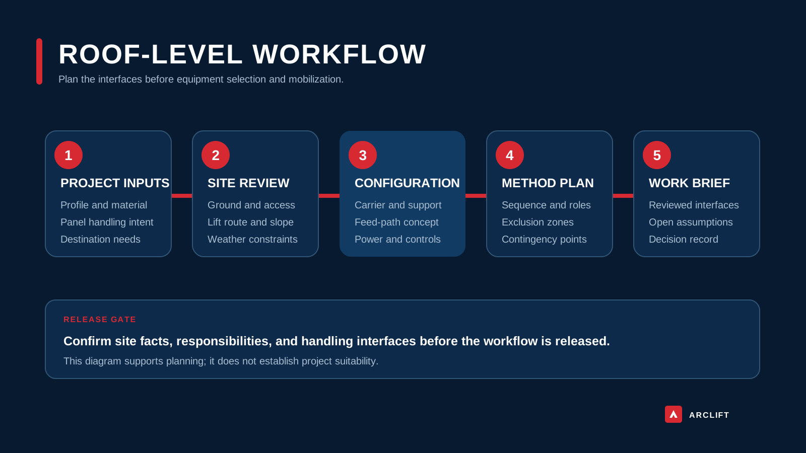
Editorial diagram. It shows a crawler architecture for discussion, not verified ground pressure, reach, travel performance, or a selected model.
Trace the machine from port to work face
A crawler system needs a continuous on-site movement route. Record surface material, slope changes, soft edges, drainage channels, covers, ramps, buried services, slab joints, and narrow passages. A broad open plan is not enough; the route must be checked at the actual machine envelope and turning behavior. Ground bearing review applies at setup and during authorized movement.
Repeated repositioning can favor a crawler arrangement where multiple work fronts sit within one controlled project area. The benefit depends on whether repositioning is permitted with the equipment in the required state and whether each new setup can be verified efficiently. Travel-at-height or travel-with-load must never be inferred from a family image. Those are configuration-specific operating facts.
A truck-mounted system adds a different set of interfaces. The base vehicle must satisfy destination rules for registration, axle loading, dimensions, steering, braking, emissions, lighting, and road use. The superstructure and chassis interface need coordinated drawings and responsibilities. A road-capable appearance in an image does not establish legal road status in any market.
At the work face, check turning radius, approach angle, overhead clearance, parking orientation, outrigger or stabilizer footprint, reaction loads, and escape route. A truck that transfers efficiently between projects may need more carefully planned support space at each setup. Conversely, a crawler unit that moves well on site may require separate transport equipment for public-road transfer.
Editorial diagram. It illustrates a truck-mounted layout only; chassis approval, dimensions, axle loads, reach, and operating performance remain unverified here.
What each architecture changes
Representative crawler and truck visuals illustrate that both architectures can combine related lifting and forming components. They do not show equivalence. The boom geometry, line arrangement, support system, chassis interface, controls, and transport breakdown can differ between configurations.
Crawler mobility concentrates the selection effort on site access, ground interaction, turning space, transport to site, and the rules for repositioning. It can suit a long building where the machine works through several adjacent zones. The trade-off is that inter-site transport may need a trailer, permits, loading equipment, or a defined breakdown plan.
Truck mobility concentrates the selection effort on road and chassis integration, legal dimensions, axle distribution, stabilizer use, and repeated site setup. It can suit service patterns involving separate projects or geographically dispersed work. The trade-off is that road suitability does not equal work-site suitability: a site may lack turning space, firm support zones, or the required setup orientation.
Service planning changes too. Identify who can inspect and maintain the chassis, crawler undercarriage, lifting structure, roll-forming line, controls, and power system. Local availability of routine chassis service may favor a truck solution, but only if the chassis itself is supported in the destination. A crawler solution may simplify the superstructure package yet still need planned transport and undercarriage service.
Historical records refer to several equipment classes, including 8, 11, and 20 t. These are historic equipment-class references, not personnel payloads, platform ratings, line allowances, or proof of current availability. For selection, request the exact operating mass, transport mass, component masses, support reactions, load chart, and permitted line configuration.
Project frequency should be described in operational terms. Record how many separate sites are expected, their typical distance apart, how long each work front remains active, and whether the same transport and setup resources will be available at every location. This can change the preferred architecture more than one headline dimension.
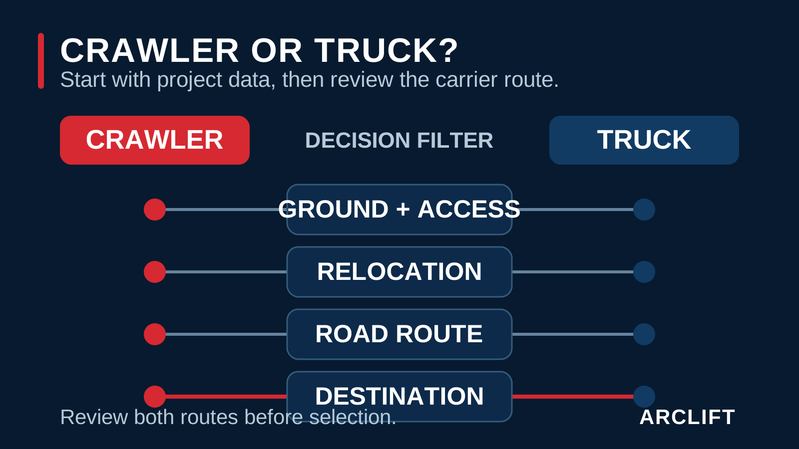
Editorial diagram. Tap to open the full-size editorial diagram. It summarizes decision variables and cannot establish which architecture, model, or performance envelope fits a specific site.
Conditions that rule either option out
A crawler configuration may not fit when site access is fragmented, public-road transfer is frequent, the available transport method is unresolved, or ground conditions cannot be confirmed. It may also be unsuitable where tight corners, weak surfaces, steep transitions, or restricted loading zones prevent a controlled route.
A truck-mounted configuration may not fit when the destination chassis interface is unclear, registration requirements cannot be resolved, axle or dimensional limits are restrictive, or the work area lacks adequate stabilizer space. It is also a poor starting point when the buyer assumes that one vehicle specification will be accepted across different markets without local review.
Neither architecture fits if the panel, coil, line, power, or roof handover process has not been defined. Do not use mobility as a substitute for a complete work sequence. Do not infer authorized travel state, personnel load, line load, wind limits, slope limits, or support reactions from editorial photographs.
If the project has only one fixed work front and a straightforward lifting plan, a mobile integrated system may add interfaces that are not justified. Compare it with a stationary line and an approved panel-handling method before proceeding.
Build a side-by-side project brief
- Mark every required working height, outreach, roof edge, forming position, and material handover zone.
- Provide a site plan showing access width, gate clearance, turning points, gradients, overhead restrictions, and work-front sequence.
- Submit ground or slab construction, allowable bearing information, weak edges, trenches, covers, ramps, and drainage features.
- Define stabilizer or outrigger space, permissible reactions, exclusion zones, leveling limits, and temporary support restrictions.
- State panel profile, material, thickness, target length, coil data, feed direction, and the intended roll-forming line.
- Describe on-site movement frequency, permitted machine state during relocation, spotter arrangements, and route-control procedure.
- Describe inter-site transport frequency, trailer or road route, container constraints, lifting points, and loading resources.
- Provide destination chassis, axle, dimension, registration, emissions, lighting, and road-use requirements.
- Confirm available voltage and power, control preferences, cable routing, environmental limits, and service access.
- List required drawings, manuals, inspection records, training, spare parts, and local compliance documentation.
For a transport-oriented truck concept, continue with the 40HQ logistics planning guide. For crawler references, review the ARC-C25 configuration page while keeping the site data above as the controlling input.
Ask for a configuration review
Send ARCLIFT the site route, ground data, required height and outreach, support-area limits, panel and coil information, movement frequency, destination road rules, chassis expectations, power supply, and transport plan. As an integrated equipment supplier, ARCLIFT can compare the unresolved crawler and truck interfaces before a project-specific quotation.
This comparison does not approve either architecture for road use, lifting work, travel, or a named site. The representative configuration images, AI-assisted editorial composite, and editorial diagram are visual aids only. They cannot prove a model identity, legal status, load, reach, support reaction, or performance. Final selection depends on signed technical data, destination requirements, and an approved site method.