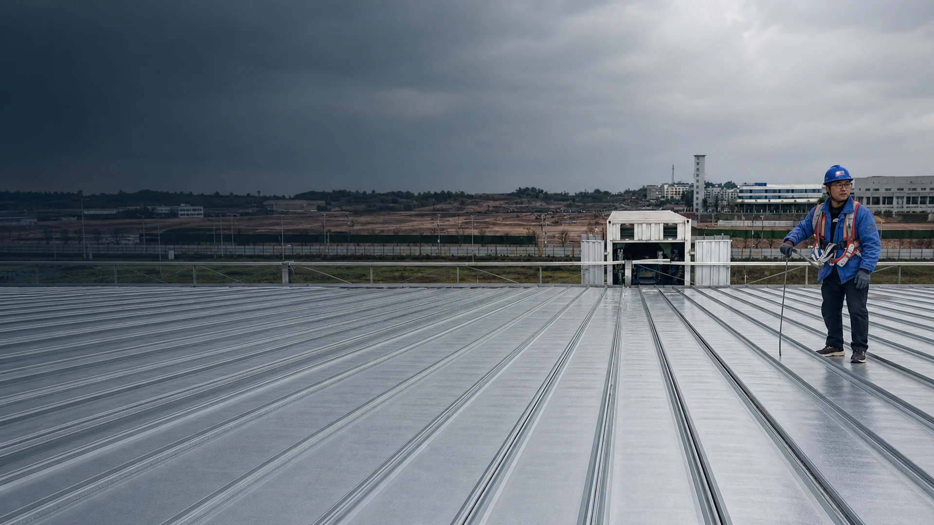
Roof-level roll forming is worth evaluating when long finished panels would be difficult to store, turn, protect, and lift from ground level, provided the forming line, coil route, support structure, weather limits, and roof handover sequence can all be engineered as one system. It is not a shortcut around lifting plans. The decision should be based on the complete material route, not panel length alone.
Start with the panel route
A roofing contractor or project engineer usually reaches this question after identifying a handling problem: the specified sheet must be formed into a panel that is awkward to move through the site once it leaves the line. Forming closer to the roof can reduce the number of transfers between line, laydown area, lifting point, and installation zone. That shorter route may be useful, but only if it remains controlled from coil entry to final placement.
The practical decision is therefore not “Can the equipment reach the eave?” It is “Can the site support a repeatable forming and handover process at the required position?” Start with the panel drawing and site route, then compare the roof-level concept with ground forming, segmented panels, or another approved handling method. The ARC-C crawler roll-forming lift range can be used as a reference when organizing those questions; the quoted configuration still needs its own technical schedule.
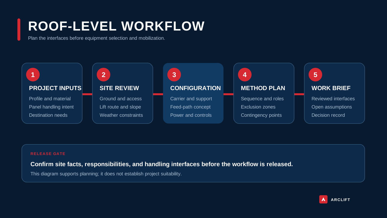
Editorial diagram. It illustrates a possible roof-level workflow, not a verified model, reach, load, or site-performance record.
Map the forming and handover conditions
Panel geometry comes first. A long, shallow profile can behave very differently from a deeper, stiffer profile of the same length. Material grade, coating, sheet thickness, strip width, seam geometry, and allowable deflection all affect how the panel should leave the line and be supported. Historic equipment records include sheet references around 0.3–1.0 mm, but that interval is not a blanket forming range. Tooling, material strength, coating response, line setup, and the proposed panel section must be checked together.
The site must then provide a workable line of movement. Map the coil unloading point, coil loading method, feed direction, equipment access route, setup zone, output direction, roof edge, and receiving crew position. A small mismatch between output direction and roof geometry can create a large handling conflict once a panel begins to emerge. Check columns, bracing, temporary works, neighboring buildings, power lines, and other obstructions in plan and elevation.
Weather is an operating condition, not a note at the end of the method statement. Wind can affect the unsupported sheet before and after forming. Rain, temperature, surface contamination, and poor visibility can alter handling and quality controls. The responsible site team should define stop-work limits and monitoring responsibilities for the actual panel and location.
Ground and support conditions remain decisive even when the forming work is elevated. The access road, turning area, working surface, slope, bearing resistance, stabilization arrangement, and exclusion zone have to suit the selected machine. If support reactions are transferred into a slab or temporary surface, obtain the necessary engineering review before selection.
Editorial diagram. Tap to open the full-size editorial diagram. It organizes project questions and does not prove that a particular machine suits a given roof or operating condition.
Where the concept helps—and what it adds
The visible equipment concept combines a lifting structure with a roll-forming line so that panel output can be positioned closer to the installation level. This representative visual illustrates the architecture only. It does not establish the model, rated height, allowable line mass, outreach, wind envelope, or compatibility with a buyer’s profile.
The main trade-off is between fewer post-forming transfers and a more integrated setup. Ground forming can simplify line access, coil change, maintenance, and power routing, while creating a longer path for finished panels. Roof-level forming can shorten that path, yet it puts more emphasis on equipment setup, line restraint, feed alignment, communication, and control of the panel as it exits.
Another trade-off concerns flexibility. A ground line may serve several elevations or buildings from a stable area, whereas an elevated configuration may need repositioning as work fronts move. Repositioning is not just travel time; the crew may have to repeat support, level, clearance, exclusion-zone, power, and communication checks.
Coil handling also stays separate from panel handling. The project must define how coils arrive, where they wait, how they are loaded, and whether the line can be replenished without conflicting with installation work. A roof-level forming concept does not by itself place the coil, provide site lifting accessories, or establish an approved lifting procedure.
Historical references across related equipment describe lift heights of approximately 12–32 m. Treat this as a family-level orientation range, not a selection table. Required height must be calculated from the working surface, roof edge, line position, output angle, outreach, and reserved clearances. The signed configuration, load chart, support reactions, and operating limits govern the final choice.
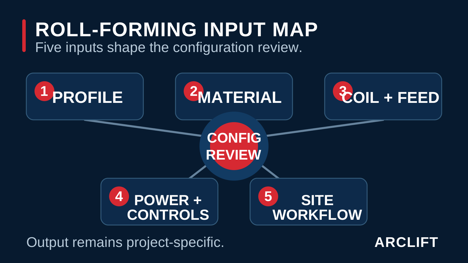
Editorial diagram. It helps identify line interfaces; it cannot verify tooling, material range, output length, electrical supply, or performance.
When roof-level forming is the wrong fit
Roof-level forming may not fit when the working surface has not been assessed, the access route cannot accept the equipment envelope, or the output path intersects the building frame. It also may not fit where wind control is inadequate, where the roof team cannot safely receive and restrain the emerging panel, or where coil loading would cross an active work zone.
Do not select this approach merely because a drawing shows a long panel. A profile may be better handled by a different forming location, temporary support method, planned lifting arrangement, or revised installation sequence. Likewise, historic references to panel output lengths of 1–200 m describe previous configuration discussions under specific conditions; they do not establish an available length for a new profile or site.
The concept does not remove the need for a site lift plan, fall protection, exclusion zones, trained operators, inspection, communication procedures, or destination-market review. Separate lifting support may still be needed for coils, line modules, accessories, setup, recovery, or parts of the installation sequence. If any of these responsibilities are undefined, the project is not ready for equipment matching.
Data to assemble before model comparison
- Provide the roof plan, elevations, eave height, working height, required outreach, and intended line position.
- Supply the panel profile drawing, material grade and coating, sheet thickness, strip width, and target panel length.
- Mark the roof slope, output direction, receiving zones, obstructions, edge protection, and temporary support points.
- State the coil mass, inner and outer diameter, unloading method, storage location, loading method, and feed path.
- Record local wind conditions, proposed weather limits, monitoring method, and the person responsible for stopping work.
- Submit ground or slab information, allowable bearing values, slope, drainage, setup area, and stabilization constraints.
- Map access width, gate height, turning points, overhead restrictions, laydown space, and the route between work fronts.
- Identify available voltage, frequency, phase, connection point, cable route, backup power, and control preference.
- Confirm destination requirements, transport restrictions, operator training, inspection duties, and required documentation.
- Describe any separate crane, telehandler, support frame, lifting accessory, or material-handling resource in the method.
Use the checklist before comparing model numbers. It will also make the discussion with the roll-forming line specification guide more useful because the line and lifting interfaces can be reviewed against the same panel definition.
Turn the route into a reviewable brief
Send ARCLIFT the panel drawing, required height and outreach, roof geometry, site access plan, ground data, coil and feed route, available power, destination, and transport constraints. As a technical selection and supply partner, ARCLIFT can organize the unresolved configuration questions before a project-specific quotation; final engineering information is still required.
This article is decision guidance, not an operating method or model approval. All photographs, representative configuration images, AI-assisted editorial composites, and editorial diagrams on this page are presentation aids. They cannot prove a model identity, rated performance, site suitability, compliance status, or a completed project result. Final equipment configuration and destination requirements must be confirmed from the signed technical schedule and the buyer’s approved site plan.