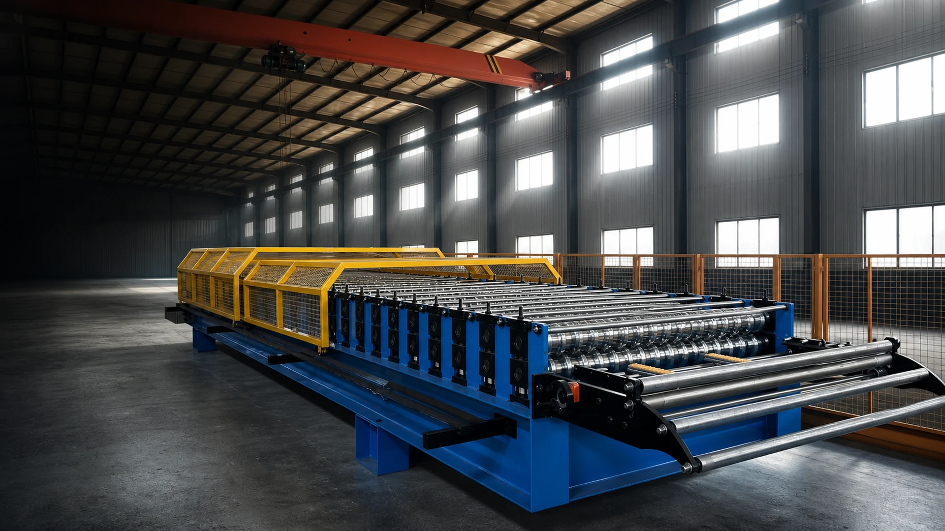
Define the panel and acceptance method before matching a roll-forming line to a lift. A useful specification includes the controlled profile drawing, material grade and coating, sheet thickness, strip width, coil data, target panel lengths, dimensional tolerances, cut method, power supply, controls, tooling scope, and downstream handling. Without those inputs, a model name or roller count cannot establish whether the line will produce an acceptable long-span panel.
Specify the finished panel first
The buyer is not selecting a line in isolation. The line must turn a specified coil into a panel that can be inspected, supported, moved, and installed under the project’s conditions. For long panels, the interfaces can matter as much as the forming stands: decoiling, feed alignment, exit support, cutting, length measurement, panel reception, and the route to the roof.
Begin with one controlled profile revision. Mark all dimensions that affect fit, seaming, drainage, fasteners, overlap, and connection to adjacent work. State which dimensions are critical and how they will be measured. If several profiles are required, identify whether changeover means separate tooling, interchangeable cassettes, adjusted spacers, or another reviewed method. The ARC-RF8 roll-forming line page can frame an initial discussion, but its images are not a substitute for a signed tooling proposal.
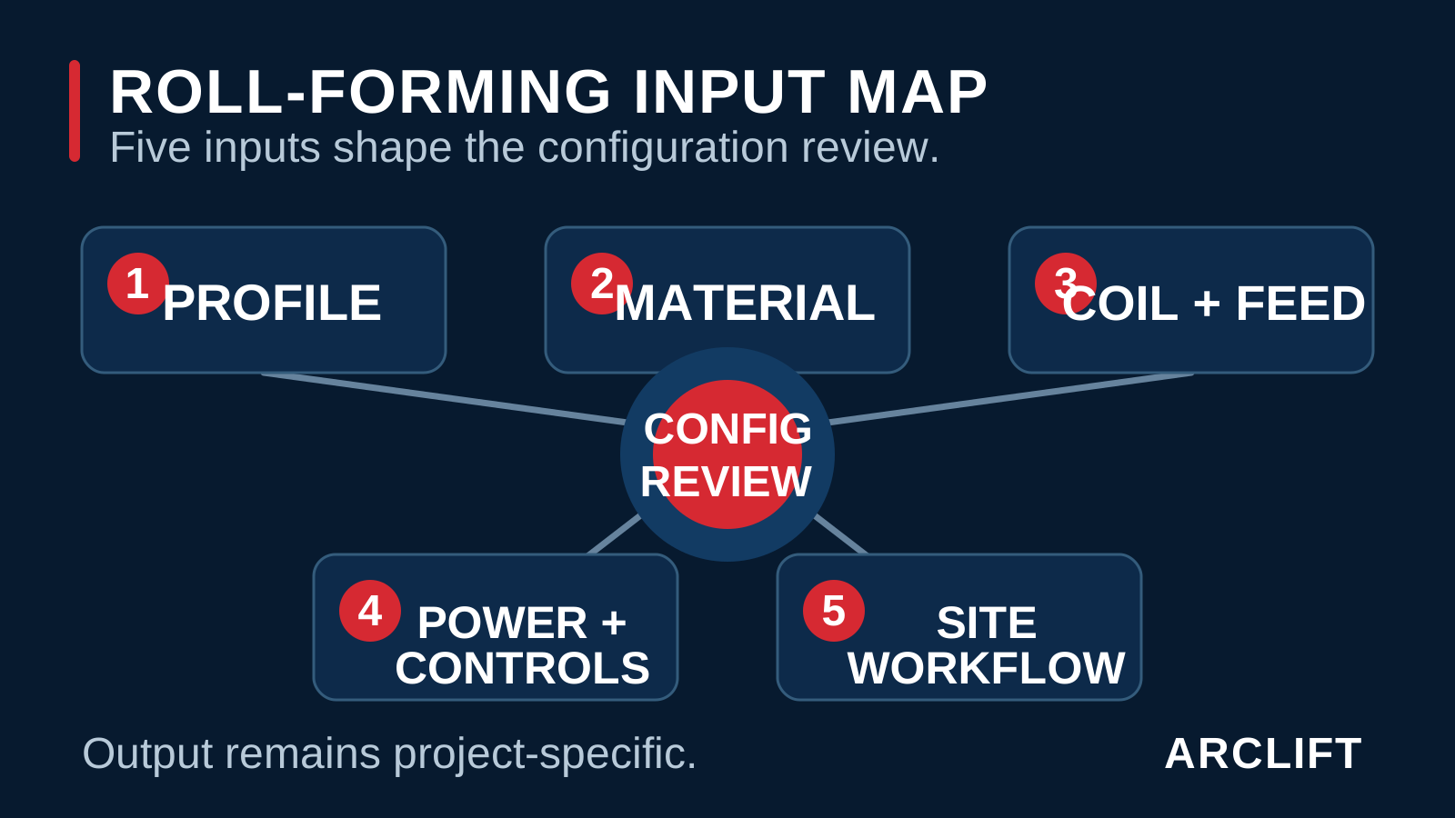
Editorial diagram. It does not prove tooling geometry, compatible material, speed, tolerance, output length, or electrical specification.
Translate the panel into line inputs
Material description must go beyond a generic metal name. Provide substrate grade, yield or tensile requirements where relevant, coating type and mass, paint or film system, surface that must remain visible, acceptable marking, and applicable material standard. Samples or traceable material data may be needed for tooling review and trial criteria.
Sheet thickness interacts with material strength, coating, bend radii, springback, roll pressure, and profile depth. Historical records contain references around 0.3–1.0 mm for related work, but that interval is conditional. It cannot be applied to a new profile without reviewing material properties, tooling, line arrangement, and acceptance tolerances.
Coil data affects the front of the line. State maximum and minimum strip width, coil mass, inner diameter, outer diameter, winding direction, edge condition, and how the coil will be loaded. Define whether the decoiler is powered, how feed tension is controlled, and what guards or restraints the project requires. Coil availability should be verified against the same data used for line selection.
Length requirements affect measurement, cutting, support, and handling. Historic documents include output-length discussions from approximately 1 to 200 m under different configurations. That is not a universal line capability. For a new project, specify the normal length mix, longest planned panel, permitted length deviation, cut-end condition, batch identification, and how the emerging panel will be supported through its full path.
Power information must include voltage, frequency, phase, permissible variation, connection method, earthing approach, cable route, environmental conditions, and any backup arrangement. A 380 V supply appears as a common historical reference, not a default for every destination. Controls, motors, protection devices, plugs, and documentation have to match the agreed project supply.
Editorial diagram. Tap to open the full-size editorial diagram. It organizes specification inputs and cannot verify line compatibility, tooling design, output quality, or operating performance.
Balance adjustment against control
A visible line can confirm broad elements such as forming stands, feed path, cutting area, frame, and control position. It cannot reveal the working roll contours, shaft loads, material assumptions, tolerance stack, control logic, or result for a buyer’s panel. Useful evidence for selection comes from drawings, agreed samples, material data, tooling proposal, test method, and configuration-specific technical documents.
More forming stations may distribute shape changes gradually, but station count alone is not a quality measure. Roll design, shaft stiffness, alignment, material behavior, support, and setup are linked. Likewise, a faster nominal line is not necessarily better for very long panels if cutting, support, communication, or installation pace controls the process.
The central trade-off is between a tightly defined line for one controlled panel and a more adjustable system intended to cover several profiles or materials. Flexibility can be valuable, but it adds setup, tooling, verification, and change-control questions that must be written into the acceptance plan.
Cutting before forming and cutting after forming create different tooling and edge considerations. The decision should account for profile distortion, burr control, coating protection, length accuracy, blade or saw maintenance, and how the panel is supported at the cut. The acceptance document should state the chosen method rather than leave it implied.
Automation can improve repeatability of length entry, batch counting, and operating sequences, yet it also introduces requirements for controls support, sensors, language, backups, electrical documentation, and troubleshooting. Select the level of control that the operating team can maintain.
Integration with a lifting system adds mass, geometry, restraint, power, communication, and maintenance interfaces. The line must fit the available mounting or support arrangement without assuming that an image proves compatibility. Review lifting position, feed direction, output path, center-of-gravity data, allowed operating states, and access for coil change and service. The roof-level forming decision guide explains the site side of that interface.
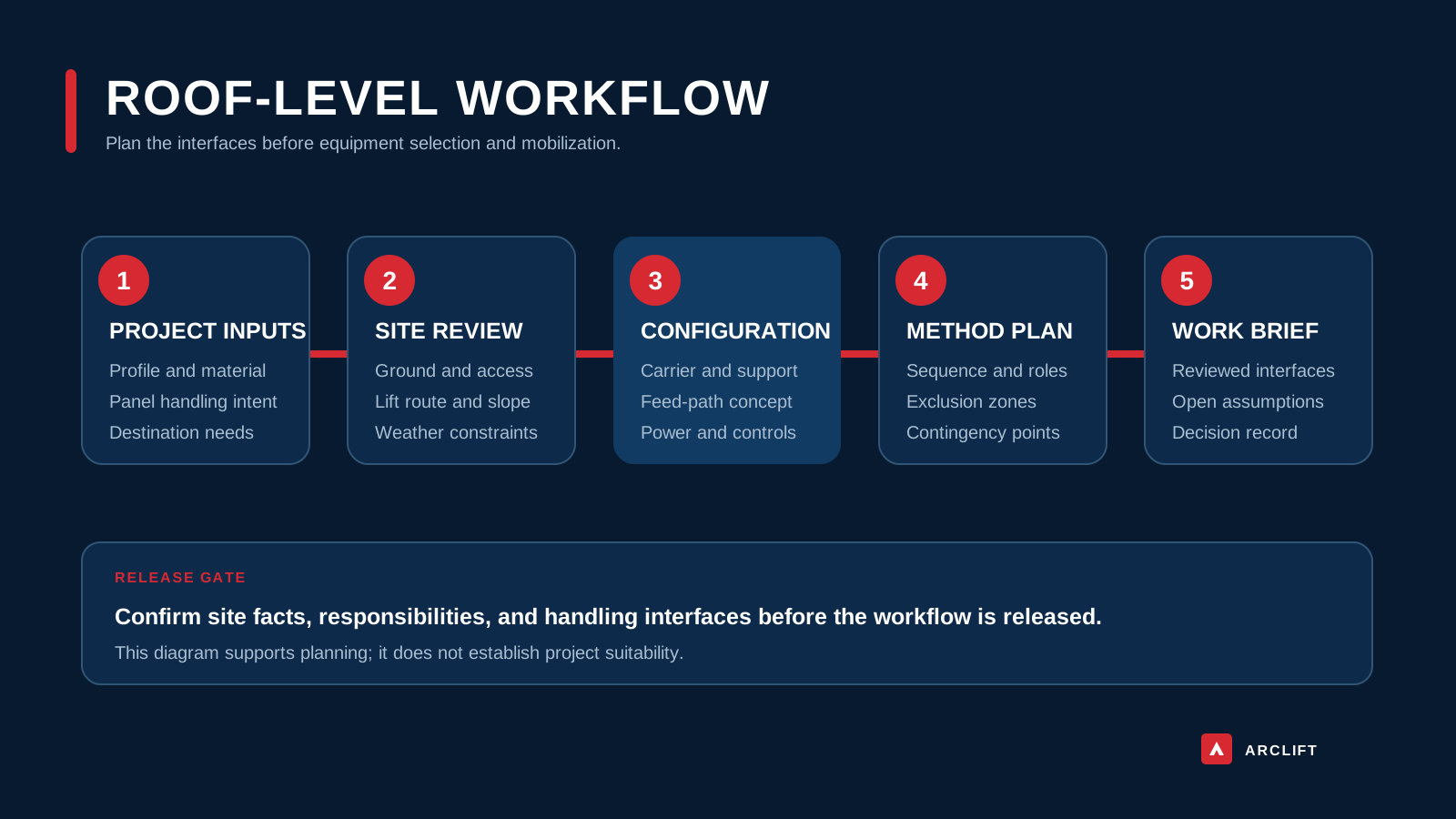
Editorial diagram. Tap to open the full-size editorial diagram. It explains workflow dependencies and cannot demonstrate a particular line, panel profile, lift model, or site result.
When the line brief is not ready
A line proposal may not fit when the profile drawing is preliminary, the material grade is unknown, or thickness is stated without tolerance and coating information. It also may not fit when coil sizes exceed the proposed decoiler, when the exit path cannot support the longest panel, or when the chosen cut method conflicts with the required end condition.
Do not accept a specification based only on a finished-panel photograph, a generic machine image, or a claimed length range. Long panels can amplify camber, twist, oil canning, marking, support, and handling problems. The acceptance method should distinguish dimensional checks, visual checks, seaming fit, sample length, and any project-specific functional review.
The forming line does not define the entire installation outcome. Coil consistency, setup, operator procedure, weather, handling supports, roof geometry, storage, lifting, and installation practice can influence the delivered panel. A line that is suitable for one material and profile may require different tooling or setup for another.
If the project needs many unrelated profiles in small batches, if source material varies widely, or if the site cannot provide a controlled feed and output route, another sourcing or forming strategy may be more practical. Resolve those operating assumptions before fixing the line architecture.
Issue a controlled specification package
- Issue the controlled profile drawing with dimensions, radii, seams, overlaps, critical tolerances, and revision status.
- State substrate, material grade, coating, paint or film, sheet thickness and tolerance, strip width, and visible surface.
- Provide coil mass, inner diameter, outer diameter, winding direction, edge condition, loading method, and feed path.
- List normal panel lengths, maximum target length, length tolerance, batch sizes, identification needs, and output sequence.
- Define profile tolerance, straightness, camber, twist, surface-marking, cut-end, burr, and sample acceptance criteria.
- Select the cutting concept and specify cut timing, edge condition, guarding, consumables, maintenance, and scrap handling.
- Confirm voltage, frequency, phase, variation limits, earthing, cable route, controls language, and available backup power.
- Describe control functions, recipes, counters, sensor needs, data retention, operator access, and service expectations.
- Map line position, entry and exit support, roof slope, working height, wind exposure, panel handover, and lifting interfaces.
- Identify destination documentation, electrical review, guarding review, training, inspection, tooling records, and spare parts.
- State the trial material, sample length, measurement tools, acceptance roles, change-control process, and record format.
Use this information when contacting any line or lifting-system supplier. It turns a vague request for “a long-panel machine” into a reviewable technical package.
Move from inputs to signed review
Send ARCLIFT the controlled profile drawing, material and thickness data, coil dimensions, target lengths, tolerances, cut preference, working height and site route, available power, destination requirements, and planned handling method. As a technical selection and supply partner, ARCLIFT can organize line and lifting interfaces for project-specific review.
This guide does not approve tooling, material compatibility, output quality, speed, length, electrical design, or a lifting configuration. The representative configuration image and editorial diagrams are explanatory visuals only. They cannot prove model identity or performance. Final selection requires signed drawings, material confirmation, agreed acceptance criteria, and configuration-specific technical documents.